
OKOSCAN UT 73HS PICKUP
The ultrasonic rail flaw detector UDS2-73 RSUI is designed for continuous mechanized testing of the rail track including turnouts (crossings, frogs) at a speed of up to 5 km/h.
The ultrasonic rail flaw detector UDS2-73 RSUI is designed for continuous mechanized testing of the rail track including turnouts (crossings, frogs) at a speed of up to 5 km/h.

The flaw detector is intended for defects detection in both rails along the running surface and rail cross-section, except for the rail base blades using flaw detection trolley during complete testing, and for the confirmatory testing of separate rail cross-sections and welded joints by means of manual probes.

The OKOSCAN 73HS System is intended for automated high-speed testing of rails laid down in a track.

Ultrasonic dual-rail flaw detector UDS2-73 SL for ultrasonic inspection of standard profile rails and tram rails

The ultrasonic rail flaw detector UDS2-73 RSUI is designed for continuous mechanized testing of the rail track including turnouts (crossings, frogs) at a speed of up to 5 km/h.

Ultrasonic single-rail flaw detector UDS2-77 SC is a manually driven cart designed for autonomous inspection of one streetcar line with rails of "groove" type and standard profile rails during .

UDS2-77 ultrasonic single rail flaw detector is a mechanized trolley intended for the inspection of one rail line. The flaw detector utilizes a unique scanning scheme that allows testing the entire rail section, except for foot flanges, by pulse echo, echo-shadow and echo-image techniques.

Sonocon BL belongs to the latest generation of portable UT instruments. Using a high-end electronics and having a richest set of modes and software features it can solve any task that can be sold with portable UT.

The Sonocon B belongs to the next generation of portable UT instruments. Using high-end electronics and having the richest set of modes and software features, it can solve any task that can be solved with a portable UT device.

USR-01 Set is intended for ultrasonic inspection of aluminothermic welded rail joints in accordance with EN14730-1 requirements. The USR-01 Set can be used for inspection of joints welded by the electrocontact method, for secondary rail track inspection based on the results of mechanized and quick systems of ultrasonic testing, as well as for pre-weld inspection of end sections of new and used rails before welding them at rail welding enterprises or in tracks.

The ОКО-22М-UT ultrasonic flaw detector is a standalone electronic unit and is intended for application in high-performance automated multi-channel NDT Systems, transportable systems (mechanized NDT systems) or for manual testing. Available in several flaw detector models that are different in number of channels and in a volume of built-in functions for results processing.

The UTG-8 is a precision Ultrasonic thickness gauge. Based on the same operating principles as SONAR.

The basic task of the eddy current nondestructive testing of railroad is to reveal head check cracking and to evaluate a damage depth in the gauge side of the rail head and the rail head running surface.

ETS2-73 is the mechanized scanning device for the manual testing by eddy-current method for presence of the surface cracks.

«Thickness Gauge +» is an ultrasonic version of Sonocon B flaw detector. It is a multifunctional next generation precise thickness gauge which combines the functionality of a traditional thickness gauge and corrosion monitor.

The UTG-8 is a precision Ultrasonic thickness gauge. Based on the same operating principles as SONAR.

TOFD 2.10 PRO Ultrasonic scanning device implements the mechanized testing of butt - welded joints of flat surfaces and pipes of medium and large diameters (with a minimum external diameter of 600 mm) and a thickness from 6 to 75 mm. Using the TOFD 2.10 PRO defects such as discontinuities, lack of fusions, cracks, porosity and slag shots can be detected and also their sizes with their coordinate dimensioning to the testing objects can be determined.

-

-

-

-

-

-

-

-

-

-

-

-

V2 Calibration Block is designed for verification of the ultrasonic flaw detectors used in the course of welded joints quality control by the UT method. It is DSTU 4002-2000 (ISO 7963, В.S.2704) compliant.

V1 Calibration Block is designed for verification of the ultrasonic flaw detectors used in the course of welded joints quality control by the UT method. It is DSTU 4002-2000 (ISO 2400, DIN 54120, B.S. 2704) compliant.

SC Block is designed for shear ultrasonic waves sensitivity calibration. It is presented with the engineering plastic storage case. The SC Block is ASTM E164 and BRR/AWS standards compliant.

AS2083 Calibration Block no. 2, IOW Type 2 Block is designed for the beam profile measurement and probe angle of the angle beam transducers (also called Beam Calibration Block). The Block is Australian Standard AS2083 and British Standard 2704* compliant.

The Notched Calibration Block (having plane angular reflectors) is designed for setting up the scan duration and sensitivity of flaw detectors used with the single crystal angle beam probes during the testing of the plate and tube products.

KMT-176 M2 Set of the Ultrasonic Plane-Parallel Thickness Standards (KUSOT-180) is designed for certification and primary checking of the contact ultrasonic thickness gauges at the manufacturing site with the thickness range of 0.6-300 mm in steel and 1-300 mm in duraluminum, as well as for the periodic verification of these thickness gauges.

Step Calibration Block is used for tuning and setting of the ultrasonic thickness gauges.

Over few decades TOFD method is widely used for fast and reliable UT of welded joints. TOFD offers great accuracy for measuring the critical size of crack-like-defects. The accuracy of better than ±1mm can be obtained in a wide range of material thickness.

Over few decades TOFD method is widely used for fast and reliable UT of welded joints. TOFD offers great accuracy for measuring the critical size of crack-like-defects. The accuracy of better than ±1mm can be obtained in a wide range of material thickness.

-

SMARTSCAN Aircraft Wheel Inspection System is intended for testing of main and nose wheels of aircrafts of various world manufacturers such as Messier - Bugatti, Goodrich, Honeywell, Maggitt and others.

The EDDYCON D universal multi-channel eddy current flaw detector is designed to solve a wide range of tasks of eddy current flaw detection.

The EDDYCON C&CL portable eddy current flaw detectors are flagships in our eddy current instrument family. They combine the best features of earlier predecessors, being furnished with 4.3" (Eddycon C) or 7.2" (Eddycon CL) display and functional buttons for immediate access to any menu of the instrument, which would meet requirements of the most demanding user.

The OKOSCAN 73HS System is intended for automated high-speed testing of rail in service.

ETS2-77 is the mechanized scanning device for the manual testing by eddy-current method for presence of the surface cracks.

EDC RAIL 5065 Eddy-Current Testing Machine is designed for automated non-destructive testing of railway rails by eddy-current method in the course of their manufacturing. The presence of surface defects such as outer surface cracks of the rail heads, flutings and railway rails base of R50, R65, R65K, 60E1, UIC60 types is tested according to DIN EN 13674-1-2017.

-

-

-

-

-

-

-

-

-

-

-

-

-

-

-

-

-

-

-

-

-

-

-

-

-

-

-

-

-

-

The ОКО-22М-EMA ultrasonic flaw detector is an independent electronic device and is designed for application in stationary high-performance systems (automated multi-channel NDT Systems), transportable systems (mechanized NDT systems) or for manual testing.

Ultrasonic Testing
Railway tracks are inspected by ultrasonic high frequency waves, usually the ultrasonic waves with a frequency of 2 to 5 MHz are used to inspect rails.
Since the defects in rails have different nature (direction of development, manufacturing defects, operational defects), different angles of ultrasound input into the rail and various sounding schemes and testing methods are used, for example: echo method, echo-shadow method, tandem methods.
Besides that, the manufacturers of ultrasonic rail testing equipment for the effective and efficient defects detection implement different types of data output to the screen, for example: A-scan, B-scan and their various combinations.
The variety of testing methods and sounding schemes, as well as various types of data visualization make it possible to effectively and with great probability detect the defects at different stages of their development.
Eddy-current testing of rails
In the rails head acting surface, as well as on the rail head running surface the quenching cracks may be developed in the process of the rails exploitation. This type of defect appears on the rail surface and develops to the depth with some time.
Timely detected and assessed defect depth in the rail head and on the head running surface allow to extend the service resource by the rail profile recovery with the grinding machines.
The eddy-current method application in this case is justified not only by a possibility to detect flaws but also by their assessment.

At the moment various rail testing technologies are used in ultrasonic rail inspection, which in turn require the participation of a person to interpret the results of their test. Different regions and countries apply their own approach to ultrasonic rail testing. There are three basic approaches to rail inspection:
Manual inspection and ultrasonic testing of rails implies using a hand-held ultrasonic flaw detector (Sonocon B) plus a set of ultrasonic transducers and a special scanning device (USR-01) with the help of which it is possible to carry out a secondary testing of railroad tracks laid, according to the results of mechanized inspection by ultrasonic or combined ultrasonic rail flaw detectors and flaw monitoring and detecting railcars, as well as for the pre-weld inspection of the end sections of new and used rails before welding them at rail welding enterprises or monitoring joints welded by electrocontact or aluminothermic method.

This type of testing involves the use of mechanized trolleys, which are moved by operator. There are two types of trolleys exist:
Such mechanized trolleys house the electronic equipment and transducer blocks, which in turn implement various rail inspection schemes.
Mechanized ultrasonic rail testers allow to carry out:
Mechanized eddy-current flaw detectors allow to carry out:

This technology lies in the fact that the ultrasonic testing of railway tracks is carried out by means of high-speed transport systems (vehicle, wagon or rail car) without stopping along the assigned route; this allows you to inspect areas exceeding 100 km per shift.
After that, the collected data is sent and analyzed in a remote location. Once the data has been analyzed and potentially dangerous sections of rail are revealed, the report is sent to the operators who are conducting confirmatory checks with the help of manual or mechanized rail flaw detectors.
The extensive range of OKOndt GROUP™ NDT equipment includes the OKOSCAN UT73HS - High-Speed Rails Testing System. This ultrasonic testing vehicle provides testing at a maximum speed of 40 km/h (25 miles) and can detect all types of crucial defects.

Eddy current non-destructive testing method is of paramount importance for technical diagnostics of aircraft parts.
The eddy current method has a number of advantages as compared to other methods, in terms of the costs of NDT equipment and consumables. This method is distinguished by high productivity, high reliability of testing and does not impose specific requirements on the quality or roughness of surface to be tested. Testing can be performed even without removing the coating or scaling.
The eddy current method is used for testing wings (fatigue cracks on the inside of wing boxes), bodies, wheel discs, engine parts (mainly - engine blades), rotors, axes, fasteners and holes (flaws in rivets, with the latter remaining in place), landing gears made of high-strength steel.
Eddy current testing is possible both at the stage of production of aircraft, helicopters or other aircraft equipment, and during on-site maintenance.
On-site maintenance of aircraft includes:
High-frequency eddy current testing | Low-frequency eddy current testing |
| (detection of fatigue or corrosion surface flaws) | (detection of fatigue or corrosion sub-surface flaws) |
| airframe parts (wings, bodies) | cracks under skin |
| landing gears (wheel discs) | cracks under repair patch |
| propellers | cracks under sealant |
| control units | cracks inside riveted joints |
| riveted and bolted joints | flaws under rivet head |
| engine blades |

This task has been successfully solved thanks to high-frequency NDT technologies which are based on the use of relatively high operating frequencies (over 1 MHz). In aluminum alloy parts, cracks can be detected at a depth over 0.2 mm, with a minimum length of 2 mm and width of 0.1 mm. In titanium alloy, austenitic and ferritic steel parts, cracks can be detected at a depth over 0.5 mm, with a minimum length of 2 mm and width of 0.1 mm. Eddy current flaw detectors are provided with pencil-type or L-shaped probes, as well as with special-purpose probes for testing blades and hole edges.


An essential advantage of the eddy current non-destructive testing method is the possibility to detect flaws of fatigue and corrosion origin in the inner layers of multilayer structures, even without removing the fasteners and without disassembling the structures. This facilitates an effective use of the eddy current method not only during the repair of aircraft, when it is possible to remove the fasteners, but directly during tests or on-site maintenance.
Based on the new design of eddy current probes, fundamentally new technologies and means for recognizing the hidden flaws in integral multilayer aircraft structures have been created, particularly, for detecting the flaws under aircraft skin at low frequencies.
Test objects
Fasteners, integral multilayer structures, repair patch in the middle of aircraft wing, shock strut pistons, riveted joints, inside parts of wing boxes, skin-stringer interface.

Another important task that can be successfully solved with the eddy current testing method is the detection of the surface defects in the holes and countersinks. These areas can be effectively and efficiently tested using rotary eddy current scanners equipped with special ECPs (reflection type) of different diameters.


This method combines a visual inspection and measurement of the geometrical parameters of welds to check their compliance with the required values. Before testing, the welds should be cleaned from scale, slag and metal splashes. After that, the surface should be treated with alcohol, or etched using a 10% solution of nitric acid. As a tool for this type of testing, a 5 or 10-power magnifier, as well as lighting devices and measuring instruments (ruler, calipers, templates) are normally used to verify both the weld and defect sizes. Despite its apparent simplicity, this type of testing is very effective and is prior to other methods. If the flaws are detected already at this stage, the weld is considered as rejected, and further testing is not performed. An obvious disadvantage of this method is the impossibility to detect the majority of hidden defects and the subjectivity of evaluation methods, which requires a lot of experience from NDT inspector.

This method is based on the ability of the liquid to penetrate into and fill the smallest capillary channels that are essentially made by weld defects. Such defects include pores and cracks that break the surface of the material. The rate and depth of penetration of the liquid depends on the radius of the capillary and the wettability of the liquid. Thus, the penetrant method is very effective for detecting surface flaws. To increase its efficiency, the so-called penetrants are used which can penetrate deep into the capillary due to their small surface tension. Their bright color makes them noticeable, which facilitates the detection of a defect. A penetrant testing kit normally includes a penetrant; cleanser for thorough cleaning of the surface before testing; developer for extracting the penetrant from the defect and creating an indicator pattern on a contrast background, using which it is possible to see the size and form of the defect. This method of testing is similar to the visual one, since it presupposes visual inspection of the weld, therefore, has the same disadvantages.

UT is one of the most common methods, because it ensures an accurate detection of hidden flaws located inside the weld. The method is based on the use of ultrasonic waves that propagate through a layer of metal and are reflected from its boundary and the boundaries of internal discontinuities. Based on the time difference between the sent and reflected signals, as well as the shape and amplitude of the reflected signals, it is possible to evaluate not only the metal thickness, but also the defects encountered on the sound path. An instrument that is used for ultrasonic testing is called ‘flaw detector’. The flaw detector utilizes special-purpose transducers (transmitters / receivers of ultrasonic signal), which allow implementing the echo pulse, pitch catch and through transmission techniques.

With the pulse echo technique, the transducer sends a probing signal to a test object and receives echo signals reflected from defects, as well as from design features of the product. Based on the time of the signal arrival, it is possible to spot the location of the defects, and based on the signal amplitude - the size of the defects. The disadvantage of this technique is the need for the defect to have a reflecting surface perpendicular to the ultrasonic beam, or be located near the surface of the product. For example, the pulse echo technique does not allow detecting planar defects (cracks and lack of fusion) that are not located close to the surface of the product under test.

The pulse echo technique does not allow detecting planar defects (cracks and lack of fusion) that are not located close to the surface of the product under test. The pitch catch techniques, Duet and Tandem, are used to recognize the above mentioned flaws. This is achieved with a pair of transducers installed so that the signal emitted by the first transducer is returned to the second transducer after reflection from the planar defect.

However, even the pitch catch mode does not guarantee the detection of all differently-directed flaws. For this purpose, the through transmission technique is used, with the transducers placed on both sides of the weld so that the signal reflected from the back surface comes to the receiver. Sufficiently large defects of almost any orientation crossing the ultrasonic beam shade the above signal, which evidences their detection. But, unfortunately, this technique does not provide exact information about the location (coordinates) of detected flaws. To obtain accurate readings from the ultrasonic flaw detector, it is necessary to make preliminary settings with the help of specialized reference blocks that are usually supplied together with the instrument. The reference blocks of various types can be also purchased separately, depending on a particular application or specific NDT task.

In recent decades, the ultrasonictime-of-flight-diffraction (TOFD) technique for weld examination has become increasingly widespread. The TOFD technique is based on interaction of ultrasonic waves with the edges of discontinuities. This interaction leads to generating diffraction waves with a wide range of angles. The detection of diffraction waves enables to establish the presence of discontinuity. The transmission time of reported signals is a measure of estimating the discontinuity height, thereby allowing to measure the discontinuity size which is always determined by the diffraction signal transmission time. The signal amplitude is not used for size measurement. Both longitudinal and shear waves are generated and applied in this case. The main information characteristic is the arrival time of the signal. The TOFD technique has a number of benefits as compared to conventional manual ultrasonic testing: Several-times higher productivity; Low sensitivity to the orientation of defects; Possibility not to estimate but measure the actual sizes of planar defects; High degree of reportability of test results. To implement the TOFD technique, special equipment is used with one or several pairs of transducers that are placed on both sides of the weld and moved along it during inspection.

Eddy current non-destructive testing is based on the analysis of interaction of an external electromagnetic field with the electromagnetic field of eddy currents induced in a test object by this field. The operating principle of ET detectors is based on the eddy current method, which consists in the distortion of eddy currents in the local test zone, followed by recording the changes in the electromagnetic field of the eddy currents that are caused by the defect and the electrophysical properties of the test object. This method is characterized by small test depths, as it is used to detect cracks and discontinuities in the material at a depth up to 2 mm. The design and setup procedure of eddy current testers resemble the design and setup procedure of their ultrasonic counterparts, using eddy current probes and eddy current reference blocks accordingly. Obviously, the ultrasonic and eddy current testing methods complement each other, ensuring a hundred-percent reliable examination of the weld over its entire depth and extent. OKOndt GROUP manufactures a series of eddy current flaw detectors for non-destructive testing of welds.

Magnetic particle inspection is a method of non-destructive testing based on the phenomenon of attraction of magnetic powder particles by magnetic scattering fluxes that arise over defects in magnetized control objects. The magnetic particle method is designed to detect surface and subsurface discontinuities such as hair, cracks of various origin, non-melting of welded joints, floken, sunsets, tears, etc. The Magnetic Particle Flaw Detector allows you to control various shapes, welds, internal surfaces of the holes by magnetizing individual controlled areas or the product as a whole with a circular or longitudinal field created by a set of magnetizing devices powered by pulsed or direct current or by using permanent magnets.

Radiography is described here only with the aim to provide a complete picture of NDT methods that are used for welds examination. Although this method is quite rigorous, its application is rather limited because it is associated with the use of gamma rays and X-rays with high permeation power, which allows them to pass through the metal, whilst the defects are recorded on the film. This increases danger to human health. In addition, instruments of this type are quite expensive. So, this is a very specific testing method that requires the use of appropriate personal protection equipment, as well as the creation of laboratory conditions for testing. Thus, we have considered the main methods of non-destructive testing of welds. It is obvious that the combined use of ultrasonic, eddy current and magnetic particle inspections ensures the most accurate test results and the safe test conditions.

For easy tasks not requiring structural data storage or corrosion mapping, a simple, reliable and easy to use ultrasonic corrosion gauge UTG-8 is used.
The device operation is maximum simplified. You have to connect the transducer, to calibrate the device on the in-built calibration block – and you may start measurements. The device also supports one-point and two-point calibrations.
When taking measurements there is also a so-called gauging accuracy indicator displayed on the screen – the more it is filled, the more accurate measurements are.

There is also a wide range of tasks, where it is required not only to measure the remaining thickness and search for corrosion damages, but also to analyze the whole measurements picture, their statistical analysis, measurements database and test reports formation. In order to solve these tasks, there are the Sonocon devices family made by OKOndt Group: Sonocon B and Sonocon BL. The devices have the same set of functions differing only by their form-factor. Sonocon B can be easily fit in your hand and weighs only 2 lb, though it is equipped with 800×480 pixels and 4.5 in display. Sonocon BL has 7.5 in diagonal screen with the same resolution, polyurethane-reinforced bumper case and extended keyboard. Meanwhile, its weight is only 3.5 lb.
Both devices have switchable software allowing to apply them as a universal flaw detectors («UT» version), and as the A-Scan ultrasonic corrosion gauges, and corrosion plotters («Thickness gauge +» version). With regards to the subject of the article, further we will speak about «Thickness gauge +» version functionality.
Both the manufacture defects – the ones that appear in the process of production – and in-service defects of fatigue type may develop (fig.1) in various metal products. The cracks may develop at different angles to the surface growing to considerable depths thus causing the threat of a product breaking when in service.
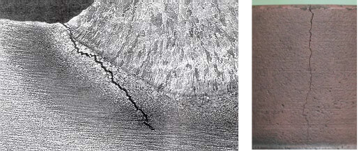
Figure 1. Cracks in metal products
The task of these defects detection can be resolved by a number of testing methods. For instance, magnetic particle, eddy current, ultrasonic and others.
The task of cracks depth evaluation is as important as defects detection is. Defects depth evaluation may be in demand in those industries where the repair of parts and products using the methods of mechanical treatment is required: turning, polishing, milling and others. Based on the value of a defect depth a decision about the utility of a part repairing can be taken, that in turn will allow to considerably decrease the costs if compared to the part replacement.
In comparison with the eddy current testing, magnetic particle method only allows to confirm whether there are cracks in the object. The eddy current testing method, additionally to the defects detection, enables to evaluate their depth.
Cracks depth can be also measured by the ultrasonic TOFD or delta method . However, their usage requires much effort and operator’s experience in comparison with the eddy current method. At the same time, the ultrasonic testing method allows to perform measuring the height of a crack not only on the scanning surface but also on the opposite side, and even of internal cracks. That is why for cases when there is no access to the surface from which a crack has started to develop, as well as for the internal cracks, it is recommended to use the ultrasonic method of testing; and to evaluate the depth of cracks developing from the test surface it is advisable to use the eddy current method.
To date, the task of evaluation of the crack-type defects is vital in such industries as
Taking into account the evident advantage of the eddy current method when dealing with crack depth evaluation and understanding the importance of this feature for industrial enterprises the developers of OKOndt implemented in their portable devices Eddycon C and Eddycon CL, as well as in some mechanized systems, the possibility to estimate defect depth, in millimeters. The correct operation of this feature requires a preliminary calibration using a calibration block. In typical cases either the flat block (fig. 2) or a flawless fragment of the test object with the artificial flaws on its surface may be used (fig. 3).
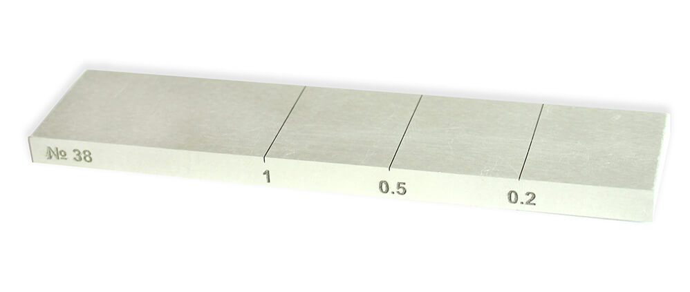
Figure 2. Calibration Block RS2353/1-3N-Fe
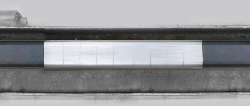
Figure 3. Calibration Block for Mechanized Rail Eddy Current Flaw Detector ETS2-77
After having performed a few simple calibration procedures, the device will calculate the depth of the surface defects in millimeters in accordance with the calibration curve that has been already built (Figure 4).
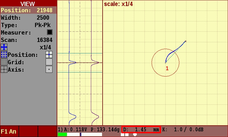
Figure 4. Flaw detector’s readings at the defect crossing on the test object
Therefore, the decision about the repair or replacement of a part is taken.
Cracks depth evaluation allows to optimize the repair and replacement processes of the industrial equipment without compromising the safety of its operation.
Using eddy current devices with the crack depth evaluation feature enables the enterprises to get a considerable economic feasibility due to a more effective inspecting of their equipment and cutting service-related expenditures. As for the railroad transport, piping and power industries – knowing the exact data about the depth of a detected crack allows to timely take the required measures thus preventing serious problems, and even disaster, that may be caused by the damaged object.

Work rolls is the main tool of the rolling manufacture, which ensures due quality of the finished rolled products. Uninterrupted operation of the powerful rolling mill and high-quality finished products depend a lot on the mill rolls surface condition and their quality

Eddy current testing System of rails EDC RAIL 5065
allows to perform an automated eddy current testing for presence of the
surface defects. Main defect types that are subject to testing by the
System are the surface defects such as cracks, laps, hairline cracks
located on the outer surface of the rail head and rail shoe of 49Е1,
60Е1, UIC60 rail types etc in accordance with EN 13674–1–2017
requirements.

Nowadays, the railway transport is one of the major means for transportation of goods and passengers. To assure the safety of cargo traffic it is crucial to use high-quality elements of the railway car wheelsets which are highly succumbed to a dynamic loading in-service. That is why the quality control during production of one of the wheelset elements, namely axles, is critical.

Ultrasonic method occupies a
special place in non-destructive testing. Being one of the first and the
most widespread it allows to detect both surface and inner defects of
various types, perform thickness gauging and non-destructive
structuroscopy.

Since early 2010, the OKOndt
Group company has been conducting scientific-and-research and
experimental-and-design works in the field of automation of the
non-destructive testing methods for the railway wheelset elements
testing. Implementation of the developed Systems for automated
ultrasonic testing AUTS Axle-4 OS-4 and mechanized magnetic particle testing OS-38
(hereinafter – the Systems) enabled the enterprises of PJSC «INTERPIPE
NTRP» and PJSC Lugcentrokuz a. S. Monyatovsky to promote their product
at the world market and successfully certify their quality labs for
compliance with requirements of European and American regulatory
documents.